 AirsoftGuns s.r.o.
Airsoft news from Systema, PTW Recoil Shock System
08. 08. 2016In this article Systema introduce their new PTW mechanism called Recoil Shock System. Let´s take a look what they wrote.

Major changes to the platform
Last year marked the 10th anniversary of the P.T.W. to which we have continuously been improving all of our parts throughout the years.
Meanwhile, we maximized the merits of the unit's structure to maintain the affinity of the conventional model.
In other words, as we continued to improve upon the parts, simply incorporating it with the base structure would give it the same performance as the newest model; this was our continuing promise to our loyal customers.
However, I broke this vow and we made changes (albeit partial changes) to the core platform; but indoing so we were able to achieve the new "Recoil Shock System".
In addition, the battery has now been moved from the conventional stock tube over to the magazine that is equipped with the Recoil Shock System.
Therefore, the contents of this remodeling is close to acomplete change.
We would like to introduce the details toall of the new parts.
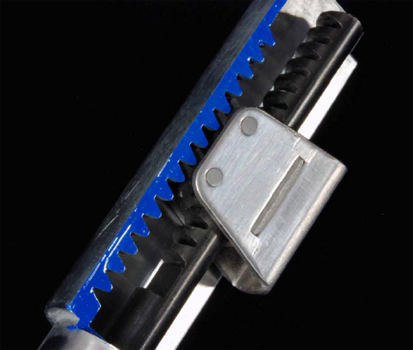
Patent Pending Recoil Shock Unit mount
New Mechanism
The mainstream method to acquire the recoil shock was conventionally brought about from the Buffer Spring structure.
Conversely, the accumulated pressure from the buffer spring and the release of the spring tension due tothe inertial force of the weight combined with the crashing force produces the recoil shock.
This also happens with GAS BlowBack guns as well, the inertial force created from full auto firing gives asense of disturbance with a feel of the whole gun pulling forward.
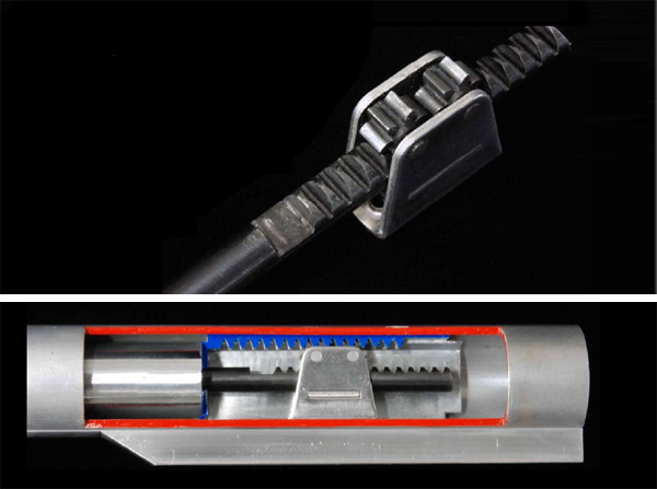
Therefore reversing the direction of the recoil weight from the Piston, in other words moving it towards the front of the gun, at the same time with the compressed spring releasing the piston allows the spring to shoot back towards the rear of the gun.
By adding one gear to the sequence of the gear progress it is possible to reverse the entire rotary direction.
By locating the parallel position of the two rack gears, the Pinion Gear is placed in between them.
Then as stated earlier, when the Piston retrogresses the weight is converted to the front, the Stock Tube Buffer Spring located towards the front is then compressed.
After the Piston has completed its rearward movement, rather than the Recoil Weight or significantly lighter Buffer Spring, it is the compressed air created by the strong Main Spring compressing the air within the Piston and the Cylinder causes the BB to fire.
Consecutively, with a slight timing delay, the weight of the shock strikes the edge of the Stock Tube due to the Buffer Spring signifying the end of one cycle.
Although the whole movement process sounds a bit complicated, the components used to create such anoccurrence is seven points, thus the mechanical reliability is quite high for this structure.
Furthermore, the primary weight caused by the Rack Gear Rod similar to the Piston Rod, is effectively designed to have a very little energy loss as it moves in a borderline to the barrel.
It goes without saying, with creation of a big recoil shockit is equally important to create components strong enough to be able to handle it.
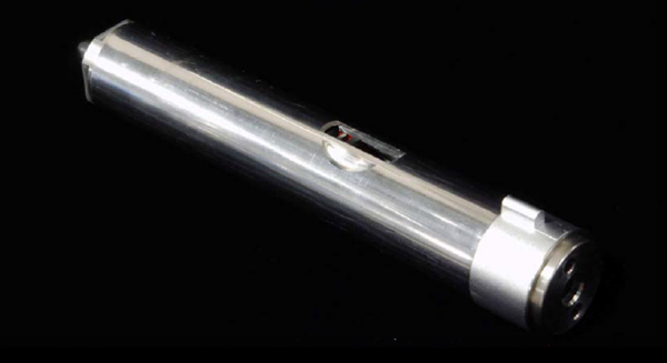
Conventionally the Stock Tube served as a role of the Battery compartment, hence it was typical to create the pipe shape for that purpose.
For the toy gun, by capping the pipe, it adds more realism to the shape of the real version.
However, our focus was to create an ever more durable performance, by adding a bowling method to our solid material we were able to achieve the production of our Stock Tube that rivals the real firearm version.
The thickness is 6mm, therefore it is just as durable for use on a real firearm.
We believe that you can enjoy firing Full Auto with peace of mind.
Recoil Pulley Gear Stand
The small gear that connects the two Rack Gear as they are seated in the parallel position is the Recoil Pulley Gear which is housed in the inner wall of the Stock Tube.
The thickness is 1.5mm made of solid stainless steel.
The majority of the load created by the recoil shock sits on that part.
The gear material used is SCM415, with our standard heat treatment.
The smaller the gear that bears heavy loads the more our company's know how shines.
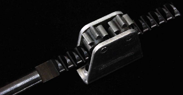
Rack Gear Rod
Generally this part is created using a die cast mold.
Of course, we create ours out of cutting them out from high carbon steel.
The external dimensions are created by high speed abrasion finishing.
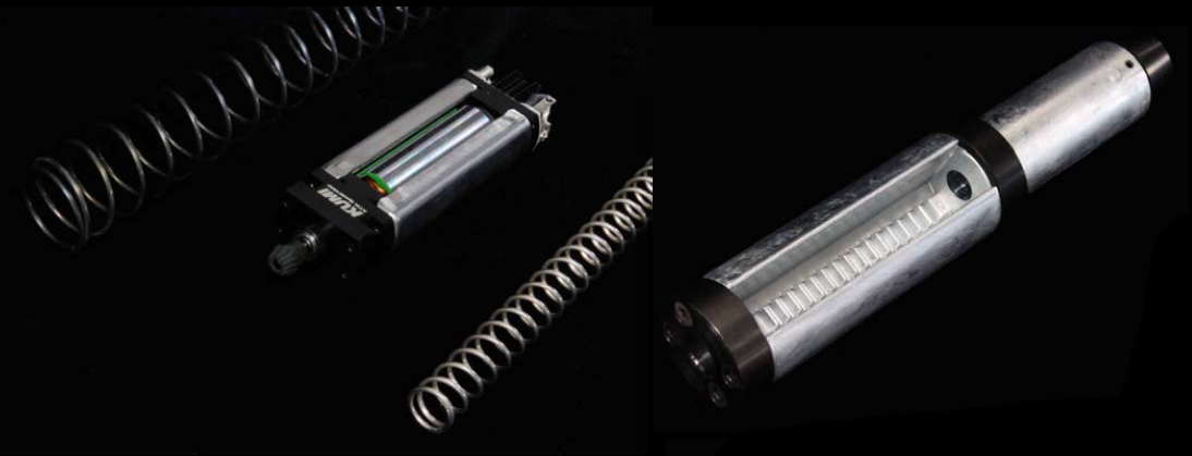
Recoil Model Exclusive Cylinder Unit
The difference from a conventional product is the piston assembly and the spring guide base, as well as the shaft.
In the exception of those Recoil Model exclusive parts, the rest are basically the same as the conventional components.
Although it being a Recoil Model, one might also want to do some surgical shooting from time to time.
In that case, simply change out the Cylinder Unit to a conventional model; which makes it very fast and convenient.
KUMI 490 type motor
The mass of our product is 269g.
If the shape was simply a circular rod, increasing the weight would be sufficient; however the Recoil Pulley Gear Stand utilizes a good deal of space which is needed to be removed, therefore that is the limitof the mass.
On the other hand, due to the large winding diameter of the Buffer Spring even if the line diameter isbig it retains it's flexibility.
In any case, in order to move heavier masses, the tension must be stronger.
Therefore, a powerful motor must be used to easily operate the Main Spring as well as the Buffer Spring.
Fortunately we have our KUMI Motor, which will make light work with the standard operations.
The Recoil System might be viewed as the focal point, however it comes only after the superiority of the basic framework.
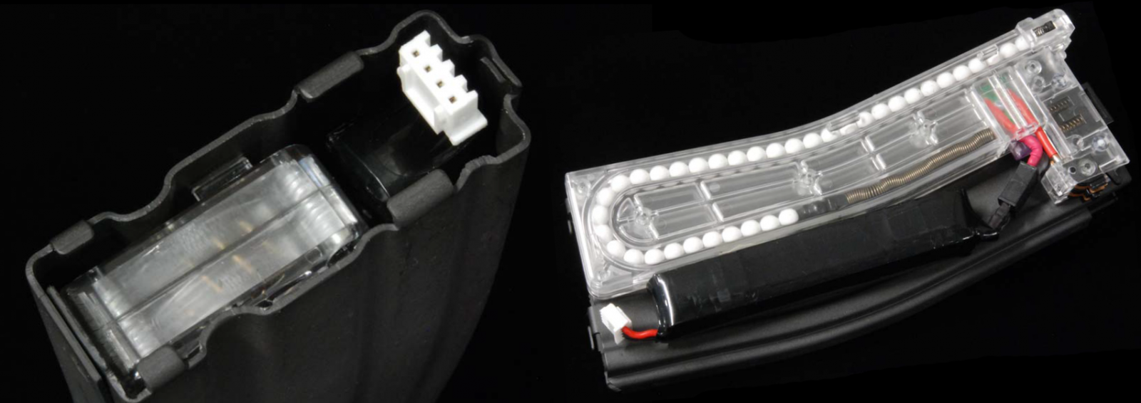
Magazine with a built-in battery
This model has the Battery incorporated within the Magazine.
The rating for this built in Battery is a new cell model rated at 800mmAh / 25C.
With a very large electric discharge property this battery will last approximately 3 cycles (of 50 roundsper cycle).
With a slightly special shape, this battery has a Micro-T connector and a balance charging cable installed in opposite directions of each other.
As a result it is possible to charge the battery with it still in the Magazine.
Simply removing the Bottom Plate will gain access to the balance charging cables.
Because the cable is rather short, there is an option to purchase an extension cable.
When charging, please remove the magazine from the receiver as leaving it in the receiver is very dangerous.
New Magazine Follower Top
The Magazine Follower Top that was adopted from the conventional Magazine.
Was a superior item that allowed every last round to fire effortlessly, however had the tendency to get lost when it got loose from the Magazine.
This version will never pop out from the magazine.
This will work with conventional magazines as well; please give it a try.
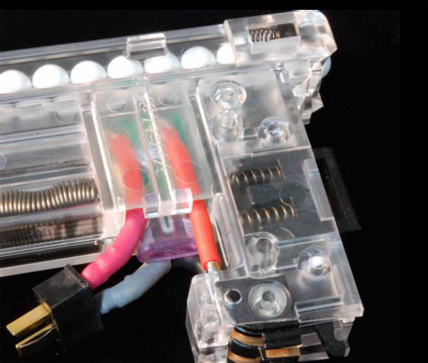
Quick Release Button
The magazine is fundamentally made to release.
Particularly in a situation where large vibrations caused by recoil shock causes an unstable environment.
When the terminals have poor contact within the magazine, it produces sparks which may cause large electric currents to drift through and that is very dangerous.
In other words, as this is certainly a possible situation it is important that it equally and thoroughly perform its release function.
That is were we thought out a plan as an added support system.
Which is our Quick Release Button.
The part located on the top of the Magazine contains two springs which the tension secures the magazine.
Therefore, even when the magazine undergoes wear, even though it may feel a bit unpleasant, due to theabove mentioned reason, we ask that you understand.
We ask that the release of the magazine be handled like a precise instrument.
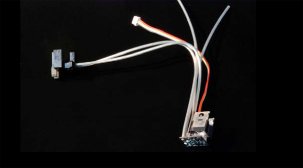
Standard features of the Micro Switch Device
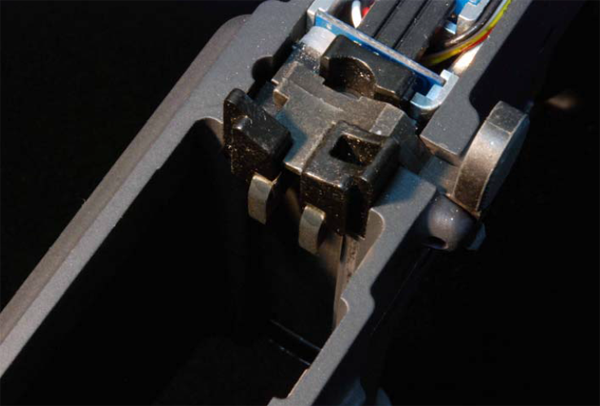
In order to achieve the Recoil Shock Unit, two essential parts are needed; these are the KUMI Motor and the Micro Switch Device.
Any more parts compartmentalized in this dense accumulation for this size would be impossible.
The location where this sits is a small gap at the edge of the end of the lower receiver.
Because the semiconductor used allows for high current to pass through, in the event that a large amount of current passes, tremendous amounts ofheat is dispersed, therefore it is seated within a sheet of silicon.
Fortunately, the material base of the M16 lower receiver is made of Aluminum, hence the whole lower receiver can be made to be a heat sink.
Due to the position of where it is situated, it is easy to spot the heat dissipating after full auto firing, even during winter.
Recoil Model Exclusive Lower Receiver
For a long time, it has been inconceivable to change the core inner dimensions of the Receiver of the conventional model.
This time, the lower receiver has undergone changes to the location where the Micro Switch Device is installed as well as the B Connector (side of the receiver) is located; these were necessary configuration changes.
The processing dimension changes were shown at the time of release of our Micro Switch Device, therefore we ask those wish to modify their receivers to inquire with your nearest P.T.W. dealer specialist.
Warning for those who purchase a similar product without the original carved seal.
In addition, those who with to purchase a Recoil Model exclusive Lower Receiver may submit their original serial number and we will add that serial number and the carved seal onto the new receiver.
Please consider doing so.
Recoil Model Exclusive Gear Box Case
For the Recoil Model, both the Micro Switch Device and the B-Connector are necessary components, therefore two power supply cables are attached to the side of the Gear Box.
The exclusive processing for the Cable routing is done.
This prepares the Ambi-Selector for use.
For those who wish for a single side selector, please use the Selector Cap on the opposite side of the Selector.
A/B Connector
Connector A is the powersupply cable terminal locatedon the Magazine side, meanwhile Connector B is the terminal support cable locatedon the side of the main gunbody.
Both are made of glass polycarbonate which is strong against high amounts of electrical current.
It is very dangerous to attempt to release the magazine while the main body is in a take down position, as a large load may affect the terminal components.
Particularly with the B-Connector, as it is attached to the Micro Switch Device, therefore a careless error could lead to dire consequences.
Recoil Model Exclusive Bolt Stop
Due to the fact that theB-Connector requires a certain amount of space to be set, the Bolt Stop has also become an exclusive part for the Recoil Model.
It is truly unfortunate that the very popular conventional magnetic bolt stop had to be replaced for the recoil exclusive model.
The Bolt Stop Spring that accompanies the Bolt Stop is the standard version.
Recoil Model Exclusive Stock Set Plate
For insulation of a terminal for asubstrate, it's the design with the polycarbonate board.
Regarding the release of the Challenge Kit
We regretfully state that, for the Recoil Model, we plan to sell the finished product for the time being.
We are sorry to those who wish to purchase the Challenge Kit.
One of the reasons for our decision was the degree of difficulty it takes to manage the cable connections of the Micro Switch Device (as mentioned above).
Once we gather enough materials and information to complete a thorough assembly manualwe may contemplate a release date for the Challenge Kit.
We kindly ask for your patience.
Model
Once the setting is done, even for us it is an unbelievably durable Recoil Model.
However, getting the setting just right takes a very long time.
Therefore, for the Recoil Model we would like to limit the sale of this model to the MAX2/Ambi Model only at this time.
We would like to mention before hand that the notion of changing out the Main Spring (that undertaking) would lead to the greatest regret that one could ever make.
Conclusion
The GAS BlowBack model uses compressed GAS as it's energy source rather than gunpowder/combustion as it's primary driving force, hence the outer appearance and it's dimensions canreplicate the real firearm very closely.
Even if you close one eye to the shooting performance, collectors and hobbyists should bequite satisfied at the details.
On the other hand, AEG users traditionally only discuss the performance of shooting.
Our story has always been to improve and develop the precision and performance which we have established as our crowning achievement.
However, this time around when we created our Recoil Model, what we felt while producing this was simply the fact that it was tremendously fun.
The mechanized sound that would overpower regular conversations, the noise associated with the compression of the Buffer Spring, and the jolt left on the shoulder, please give this a try.
.png)